
BESS Compliance: Grid Code, Fire Safety & Approval for C&I and Solar
BESS Compliance: Grid Code, Fire Safety & Approval for C&I and Solar
For a commercial and industrial (C&I) or solar-plus-storage battery energy storage system (BESS), compliance is a translation problem before it is a paperwork problem. Three requirement streams — the local grid code and the network operator's grid-connection approval, protection coordination between the BESS, the PV inverter and the site distribution system, and the fire-safety requirements applied by the authority having jurisdiction (AHJ) — must each be converted into individual specification lines while the purchase order can still be changed.
The conversion is driven by five application assessments: load-profile assessment, time-of-use (ToU) tariff analysis, PV generation assessment, export limitation, and backup-load assessment, with coordinated PV–battery control tying the last two together. Each assessment settles a different part of the specification and produces a different document in the approval file. This guide works through that sequence for C&I and solar-plus-storage projects. Utility-scale interconnection studies and critical-facility resilience roadmaps follow a different sequence and are outside this scope.
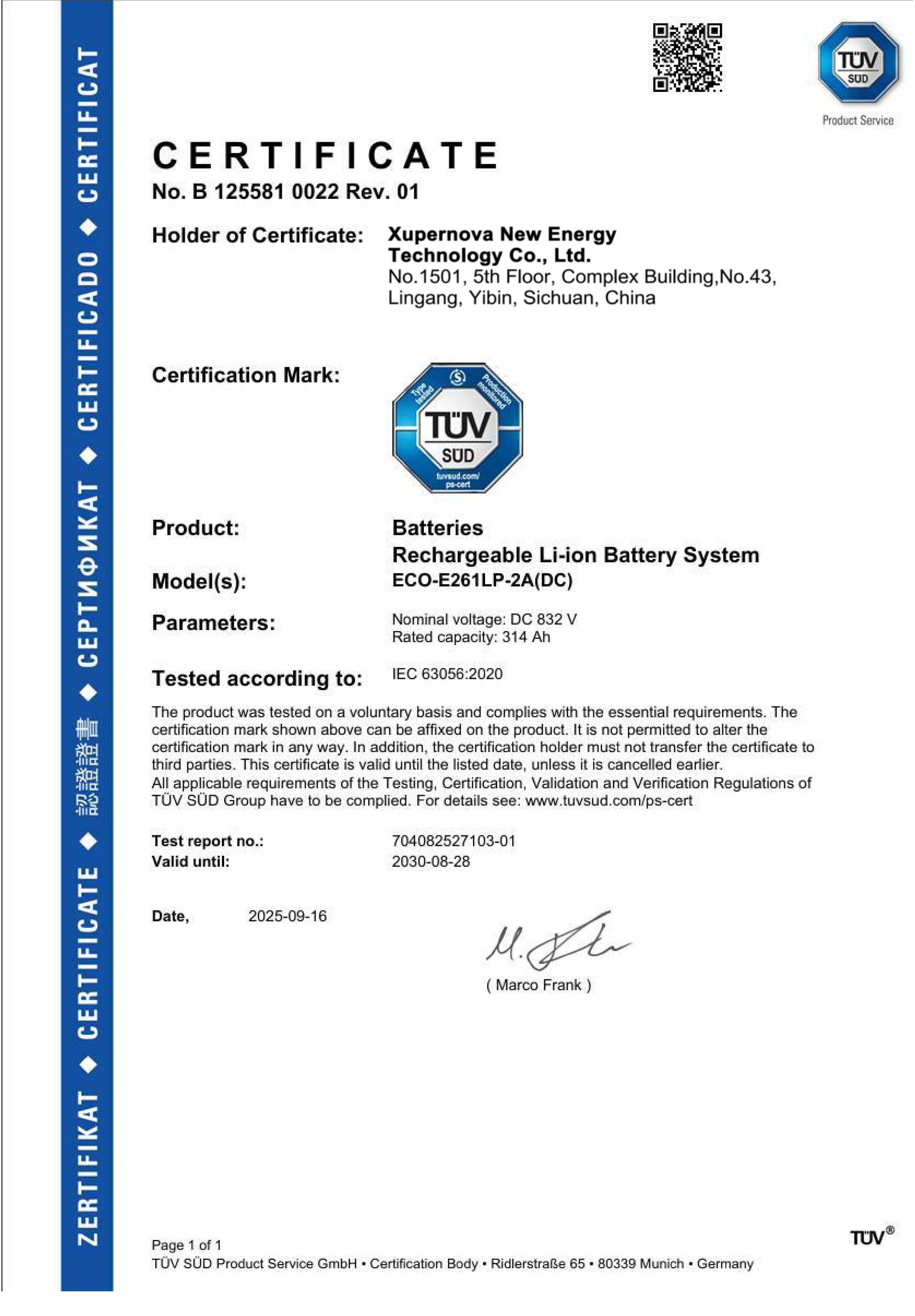
IEC 63056:2020 product certificate for the ECO-E261LP-2A battery system, issued by TÜV SÜD Product Service GmbH under certificate number B 125581 0022 Rev. 01.
Why a Product Certificate Does Not Equal a Grid-Connection Approval
A certificate is a statement about a model, a standard version and a market. It is not a statement about a site. Xupernova New Energy Technology Co., Ltd. (Xupernova) is an energy storage and new energy solutions provider whose business coverage includes Europe, North America, South America, the Middle East and Asia, and whose C&I and solar-plus-storage products carry the certificates discussed below. Those certificates answer equipment questions; the network operator answers the installation question, after reviewing connection data, protection settings and commissioning results.
The equipment evidence itself splits into three families that are often confused in a tender package. Electrical safety of the converter assembly is addressed by the LVD Attestation of Conformity against EN 62477-1:2012/A12:2021, certificate number N8A 125581 0024 Rev. 00, issued for the EU market and covering the ECO-E261LP-2A at 125 kW, 261.248 kWh, IP55. Electromagnetic compatibility is addressed separately by an EMC Attestation of Conformity against EN IEC 61000-6-4:2019 and EN IEC 61000-6-2:2019, certificate number E8A 125581 0023 Rev. 00, again for the EU market. Battery-system safety is addressed by the IEC 63056:2020 product certificate, number B 125581 0022 Rev. 01, whose scope is the Rechargeable Li-Ion Battery System ECO-E261LP-2A(DC) rated DC 832 V, 314 Ah. A grid code is a fourth and different layer, applied at the point of connection.
Each document names a model in its scope, and that name is a control point. The Italian compliance documents refer to the ECO-E261LP-2A, not to a generic product family. Before a certificate is reused in a tender or an approval file, the buyer should confirm that the exact nameplate model, power rating, energy rating and enclosure rating in the scope match the equipment being ordered. A certificate carried over to a differently rated model, even within the same product family, does not transfer its validity.
Market Context: Why Compliance Now Sits Inside Procurement
Deployment volume explains the pressure. The IEA's Global Energy Review 2026 reports 108 GW of new battery storage capacity commissioned globally in 2025, and the same review puts LFP at approximately 90% of global battery storage deployments. In the United States, the EIA's Preliminary Monthly Electric Generator Inventory projects utility-scale battery capacity growth of 19.6 GW in 2025. These figures describe market-level deployment; they say nothing about any individual project's approval timetable, which remains site- and operator-specific.
Two practical consequences follow for a C&I or solar-plus-storage buyer. First, with LFP chemistry now dominant, chemistry selection rarely differentiates competing offers; the differentiator moves to configuration, evidence and approval readiness. Second, as connection queues lengthen, a specification that has to be reworked after the study comes back costs more schedule than a specification that anticipated the study. Compliance work therefore belongs in the technical specification, not in a post-order documentation phase.
The Requirement-to-Specification Map
The table below is the working model for the rest of this guide. Reading it left to right shows how a regulatory or operator requirement becomes a line item a supplier can quote against, and then becomes a document the approval file can hold.
| Requirement stream | Assessment that defines it | Specification line it controls | Evidence the file needs |
|---|---|---|---|
| Grid code and grid-connection approval | Load-profile assessment; PV generation assessment | PCS rating, connection voltage, interface protection, communication protocol | Market certificate for the exact model; operator application and approval |
| Protection coordination | Load-profile assessment; PV generation assessment | Relay settings, grading with the PV inverter, transformer and switchgear scope | Protection study, settings schedule, commissioning records |
| Export limitation | PV generation assessment; export-limit instruction from the operator | Metering point and CT location, EMS control logic, dispatch priority | Control narrative, set-point records, witnessed test at the point of connection |
| Fire safety | Site layout and AHJ review | Fire protection system, enclosure and layout, IP rating, labelling | Equipment test evidence, layout drawings, emergency response documentation |
| Backup and islanding | Backup-load assessment | STS/EPS scope, protected-load list, islanding protection, black-start behaviour | Load schedule, transfer test, operating procedure |
The Five Application Assessments That Set the Specification
Step 1 — Load-profile assessment: separating power from energy
A load profile answers two different questions that are frequently merged into one number. The peak of the curve sets the power rating; the area under the curve inside the discharge window sets the energy rating. A site with a narrow, sharp peak and a site with a long plateau may need the same kW but very different kWh. For C&I peak shaving, the assessment should output the maximum import limit to be respected, the intended charge and discharge windows, and the required C-rate, which determines whether 0.5P, 1P or 2P operation is specified.
The same assessment fixes the balance-of-system scope around the battery. A C&I peak-shaving installation is normally specified with a grid-connection cabinet, a transformer if required, switchgear, a smart meter, CTs, a plant-level EMS, power cables and communication cables. Each of these items sits somewhere in the approval file, so leaving them outside the battery quotation does not remove them from the project — it only moves them to a later stage, usually with less schedule margin.
Step 2 — ToU tariff analysis: converting a tariff into a dispatch window
A time-of-use tariff translates into a control schedule, and the schedule translates into hardware decisions. One discharge window per day and two discharge windows per day produce different daily throughput, different thermal load and different economic logic. Where the tariff creates a long daily cycling duty, a liquid-cooled cabinet such as the XA-C0261-L1 — 125 kW rated power, 261.25 kWh rated energy, 0.5P/1P/2P, IP55, −30 °C to 55 °C — is the relevant class of equipment. Where the site is small-scale and the cycling duty is lighter, an air-cooled cabinet such as the XA-H0064-A1 at 25–50 kW and 64.54 kWh may be the appropriate specification.
The tariff analysis is also an approval input. Demand-limit control, load-following control and scheduled charging all change what the site draws from the network at specific times, which is exactly what the operator reviews. Writing the control mode into the specification prevents a commissioning-stage argument about whether the EMS should follow a schedule, a demand ceiling, or both.
Step 3 — PV generation assessment: sizing the solar side before choosing a topology
On a solar-plus-storage project, the PV generation assessment determines the DC and AC interfaces the storage system must accept. This is a specification decision, not only a yield calculation. The XA-H0261-L1, a liquid-cooled solar-plus-storage cabinet rated 261 kWh with 0.5P/1P/2P operation and IP55 protection, is designed for C&I solar-plus-storage and microgrid applications; the XA-H0064-A1 covers small-scale C&I solar-plus-storage at 25–50 kW and 64.54 kWh.
The interface width matters at approval stage. In one delivered C&I solar project, 32 units of a 500 kW / 1.044 MWh liquid-cooled solar-plus-storage configuration were deployed with up to 1 MW of PV input, an arrangement that relies on a wide PV input range, modular expansion and a plant-level EMS. A narrow PV input window would have forced a different inverter architecture — and a different approval drawing set.
Step 4 — Export limitation: a grid instruction that becomes metering and logic
Export limitation is the requirement most often written as a sentence and then discovered to be an engineering task. Limiting export at the point of connection requires measurement at that point — a smart meter and CTs placed where the operator says, not where cabling is convenient — plus EMS logic that decides what happens to surplus PV when the export ceiling is reached. The realistic options are curtailment of PV, diversion into the battery, or a priority rule combining both.
Because that priority rule changes measured behaviour at the connection point, it belongs in the specification and in the witnessed commissioning test. A zero-export or capped-export site that is commissioned against an undefined control narrative tends to be re-tested, and re-testing is a schedule risk rather than a technical one. Export limitation requirements, grid-code compliance and coordinated PV–battery control are the documented special requirements for C&I solar-plus-storage and PV self-consumption applications, which is why they should be addressed as one package.
Step 5 — Backup-load assessment and coordinated PV–battery control
Backup scope is defined by a load list and a duration, not by the battery capacity alone. The assessment should record which circuits are protected, the required backup duration, whether zero-interruption loads need a UPS, and whether a diesel generator remains in the architecture. On the equipment side, backup operation is delivered through an STS or EPS cabinet together with grid-forming capability, and it must be specified explicitly, because backup is a configuration option rather than an automatic property of a grid-following system.
Coordinated PV–battery control closes the loop. In a delivered C&I park project, 12 units forming a 1 MW / 2.088 MWh solar-plus-storage microgrid used an integrated STS with grid-connected and off-grid switching, PV and diesel generator interfaces, and centralised energy management. The compliance lesson is that islanding protection, the protected-load list and the transfer sequence are all reviewable items — they need to exist as documents, not as commissioning discoveries.
Building the Grid-Connection Approval File
The document set is defined by the network operator in each market, so no universal list applies. What is consistent is the structure: a data layer, a design layer, a settings layer and a proof layer. A workable file normally contains the following, adapted to local requirements.
- Connection data — requested import and export capacity, load profile, PV installed capacity, single-line diagram.
- Equipment evidence — the certificate or attestation for the exact model, with standard version, certificate number, issuing body and market scope.
- Protection and control design — interface protection settings, grading with upstream and downstream devices, control narrative for export limitation and dispatch.
- Fire-safety submission — layout, separation and the equipment-level evidence the AHJ requests.
- Commissioning test plan and results — witnessed tests at the point of connection, including export-limit verification.
- As-built documentation and operating procedures — settings schedule, emergency response documentation, maintenance instructions.
Italy illustrates how the equipment layer supports the file. The ECO-E261LP-2A holds CEI 0-21:2022/V2:2024 certification under certificate number D 125581 0027 Rev. 00 and CEI 0-16:2022/V3:2024 under D 125581 0028 Rev. 00, both issued by TÜV SÜD Product Service GmbH for the Italian market. In a retail deployment, 50 units of the 125 kW / 261.248 kWh class were operated for peak shaving, time-of-use arbitrage and PV self-consumption, with compatibility with Italian grid requirements listed among the delivery highlights. The certificate supported the equipment argument; the site approval remained a separate, project-specific step.
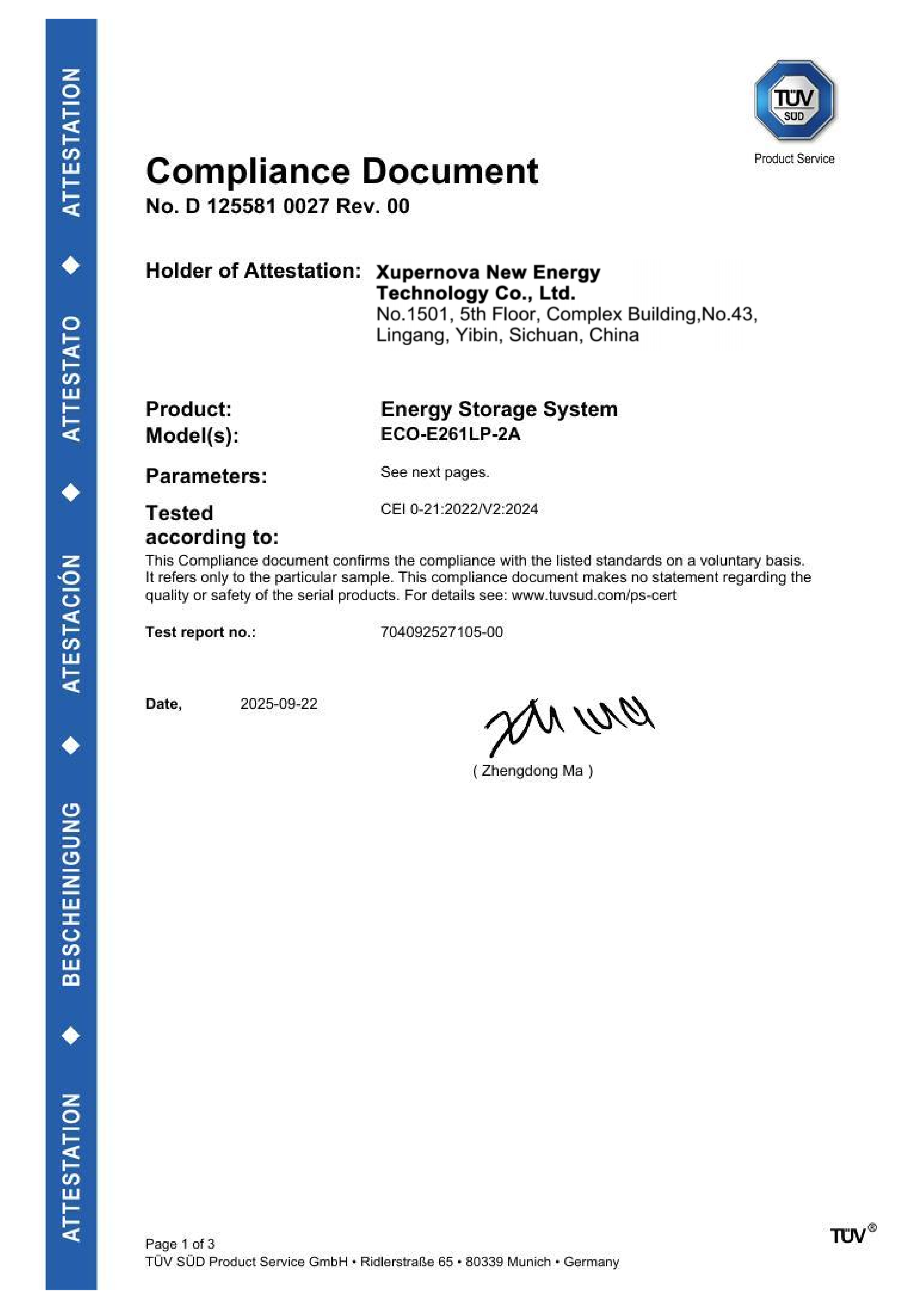
CEI 0-21:2022/V2:2024 compliance document, certificate number D 125581 0027 Rev. 00, issued by TÜV SÜD Product Service GmbH for the Italy market.
Where the project market is the United Kingdom, the same logic applies with a different standard: a 2 MW / 4.176 MWh renewable project built from seven 10-ft containers with integrated PCS, BMS and EMS lists G99 grid-code compatibility among its highlights. The certificate name changes; the review sequence does not.
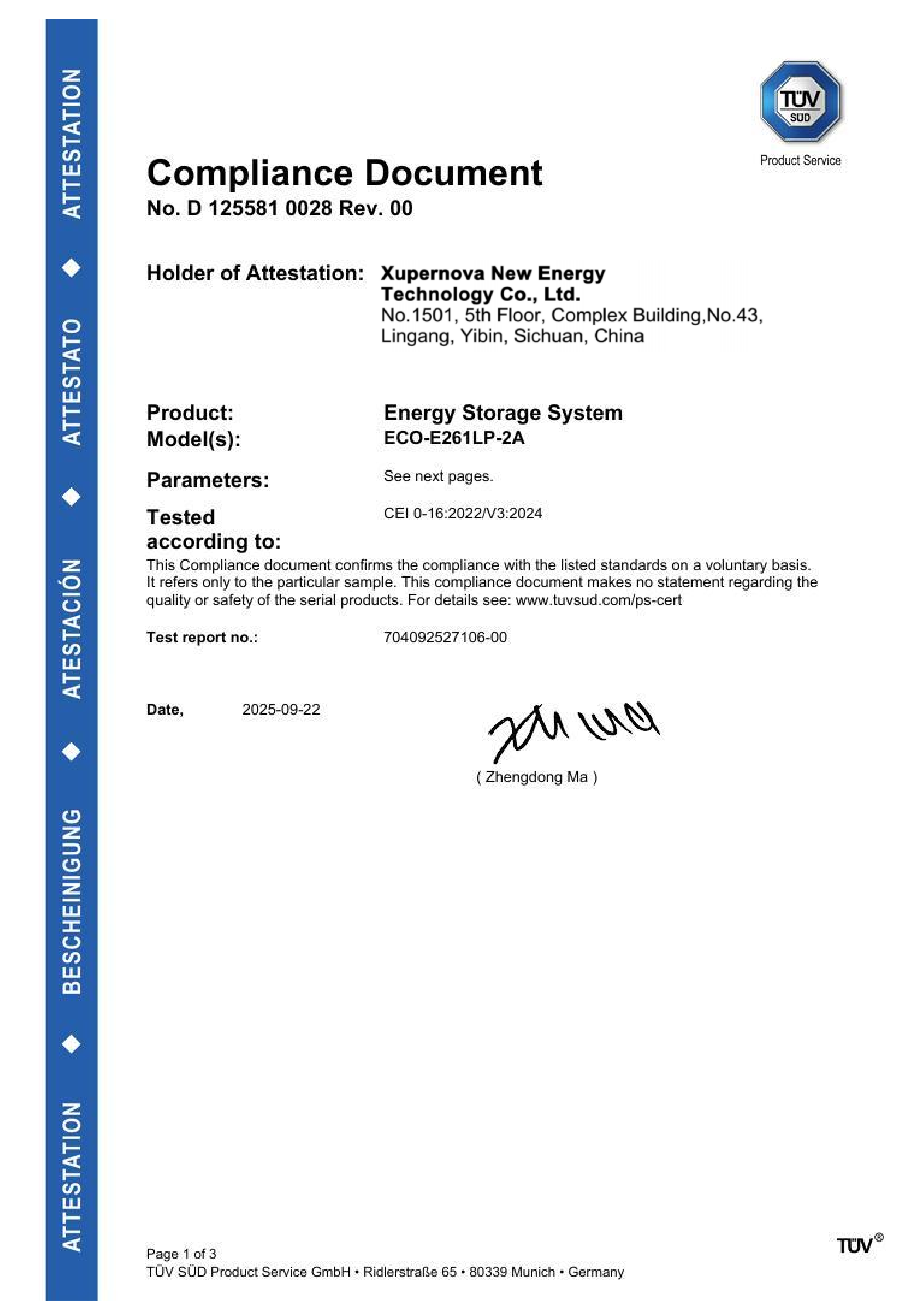
CEI 0-16:2022/V3:2024 compliance document, certificate number D 125581 0028 Rev. 00, issued by TÜV SÜD Product Service GmbH for the Italy market.
Protection Coordination: the Specification Line Most Often Left Blank
Protection coordination is where a storage specification most often has a gap, because it is nobody's default deliverable. The BESS adds a controlled current source at the site; the PV inverter already added one. Both must grade with the site's existing protection, and the settings must be documented before the operator will energise the connection. The engineering inputs are the converter's fault-current behaviour, the transformer and switchgear arrangement, and the relay schedule of the existing installation.
Two specification practices reduce the risk. First, state explicitly who performs the coordination study and who signs the settings schedule — the storage supplier, the PV EPC contractor, or a third-party protection engineer — because a study without an owner tends to appear late. Second, treat the transformer and switchgear configuration as part of the ordered scope rather than a site-side assumption. Xupernova's OEM/ODM customisation scope explicitly includes transformer and switchgear configuration, grid code, and communication protocols, which is the practical mechanism for aligning the delivered equipment with a study that arrives after the order.
Fire Safety: What Belongs in the Specification and What the AHJ Decides
Fire safety is a separate stream from electrical conformity, and the two should not be evidenced by the same document. The AHJ sets separation distances, the detection and suppression expectations for the site, and the emergency-response documentation it will review; those determinations are local and are not inferred from an EU conformity attestation. What the project specification must do is record the configuration that will be submitted for that review, so the submitted drawings match the delivered equipment.
Four specification fields carry most of the weight. The fire protection system is a configurable item, not a fixed attribute, and it should be stated with its scope. The enclosure and IP rating should be stated numerically — IP55 outdoor protection is specified on the C&I and solar-plus-storage cabinets discussed here — while recognising that IP55 is an ingress-protection rating and not a fire rating, so it cannot stand in place of fire documentation. The ambient operating range should be stated, −30 °C to 55 °C across these models, because thermal design assumptions feed both the fire review and the performance case. Finally, labelling, layout and emergency response documentation should be listed as deliverables, not as close-out items.
Equipment-level proof supports that submission. The EMC and LVD attestations for the ECO-E261LP-2A cover the 125 kW, 261.248 kWh, IP55 configuration against EN IEC 61000-6-4:2019, EN IEC 61000-6-2:2019 and EN 62477-1:2012/A12:2021 respectively, and factory acceptance testing is available as 100% FAT covering electrical safety, functional and aging tests, with third-party inspection available on request. Those records answer equipment questions; the site fire-safety determination remains with the AHJ.
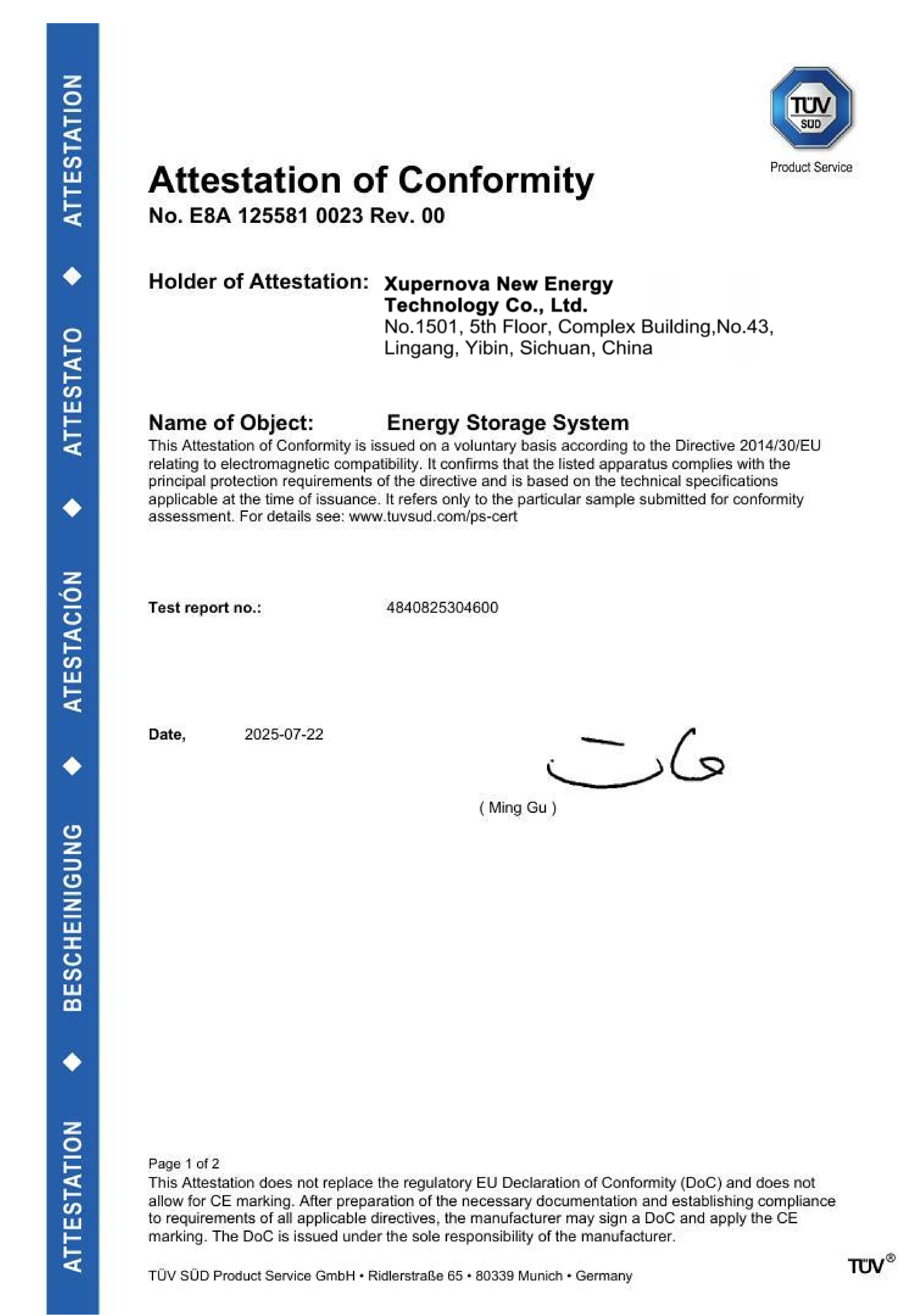
EMC Attestation of Conformity, certificate number E8A 125581 0023 Rev. 00, against EN IEC 61000-6-4:2019 and EN IEC 61000-6-2:2019, EU market.
How Delivered Projects Translate Compliance Into Configuration
Four delivered configurations show the same translation pattern at different scales. Each is described here with the details recorded for the project; results are project-specific and are not a forecast for another site.
Retail portfolio, Italy — 50 units of 125 kW / 261.248 kWh
A supermarket and retail facility operator deployed 50 units over one year for peak shaving, time-of-use arbitrage and PV self-consumption. The recorded outcome was stable daily operation with reduced peak demand and improved onsite solar utilisation. The compliance-relevant design choices were a compact all-in-one liquid-cooled format, single-unit deployment with low onsite installation workload, remote monitoring, and compatibility with Italian grid requirements. Repeated deployment of one model across many sites is where model-scope discipline pays: the equipment evidence is reused, while each site still requires its own approval.
Commercial facility and solar EPC — 500 kW / 1.044 MWh with up to 1 MW PV
Across 32 units and five years of operation, this solar-plus-storage configuration combined PV self-consumption, peak shaving, arbitrage and emergency power support, with recorded outcomes of increased solar self-consumption, reduced daytime peak demand and optimised energy costs. The design relied on a wide PV input range, modular expansion and plant-level EMS — the three features that most directly determine whether export limitation can be implemented at the point of connection without redesigning the array.
Industrial manufacturer, Germany — 1 MW / 2.09 MWh
Twenty units delivered a 1 MW / 2.09 MWh installation for peak shaving, arbitrage and demand management, with two years of stable automatic operation and reduced peak grid demand recorded. The highlights are compliance-relevant rather than commercial: an all-in-one liquid-cooled design, plant-level EMS, modular deployment, IP55 protection and compatibility with German grid requirements. For a German industrial connection, the plant-level EMS is the component that carries the control narrative the operator reviews.
Renewable developer — 2 MW / 4.176 MWh in 10-ft containers
Seven 10-ft containers delivered 2 MW / 4.176 MWh for renewable shifting, grid balancing, peak shaving and backup, with four years of operation and recorded improvements in renewable utilisation, dispatch flexibility and grid stability. The configuration combined integrated PCS, BMS and EMS, liquid cooling, multi-source access and G99 grid-code compatibility. Container format mattered here for a different reason: a compact footprint reduces the layout constraints that feed the fire-safety submission.
Matching the Model to the Requirement
Once the five assessments are complete, model selection becomes a mapping exercise. The table below lists the supplied configurations with the parameters relevant to a compliance review.
| Model | Type | Power / energy | Cooling | Protection and range | Application |
|---|---|---|---|---|---|
| XA-C0261-L1 | All-in-one ESS cabinet | 125 kW / 261.25 kWh | Liquid | IP55; −30 °C to 55 °C | C&I energy storage |
| XA-H0261-L1 | Solar-plus-storage cabinet | 261 kWh; power rating not stated in supplied specification | Liquid | IP55; −30 °C to 55 °C | C&I solar-plus-storage, microgrids |
| XA-H0064-A1 | Solar-plus-storage cabinet | 25–50 kW / 64.54 kWh | Air | IP55; −30 °C to 55 °C | Small-scale C&I solar-plus-storage |
| XA-X1044-L1 | 10-ft all-in-one container | 500 kW / 1044 kWh | Liquid | IP55; −30 °C to 55 °C | C&I, microgrids, backup power |
| XA-X2170-L2 | 20-ft all-in-one container | 1125 kW / 2170.3 kWh | Liquid | IP55; −30 °C to 55 °C | C&I, grid-side storage |
| XA-V5015-L1 | 20-ft battery container | 5.015 MWh | Liquid | IP55; −30 °C to 55 °C | Grid-scale, C&I |
All models support 0.5P/1P/2P C-rates and use Grade A LFP lithium-ion cells from BloombergNEF Tier 1 energy-storage cell manufacturers, with semi-solid-state, solid-state and sodium-ion options subject to project requirements, technical validation and availability. Where a parameter is not stated above, it should be confirmed at RFQ stage rather than assumed.
A Pre-Order Verification Checklist
- Match the certificate scope to the nameplate. Confirm the model name, kW rating, kWh rating and IP rating inside the certificate scope are identical to what is being ordered.
- Check the standard version, not just the standard number. CEI 0-21:2022/V2:2024 and CEI 0-16:2022/V3:2024 are version-specific records; an older edition is a different claim.
- Record the issuing body and certificate number. For example TÜV SÜD Product Service GmbH, D 125581 0027 Rev. 00, D 125581 0028 Rev. 00, E8A 125581 0023 Rev. 00, N8A 125581 0024 Rev. 00, B 125581 0022 Rev. 01.
- Separate equipment conformity from installation approval in the project plan, with different owners and different dates.
- Name the owner of the protection coordination study and require the settings schedule as a deliverable.
- Write the export-limit control narrative including metering point, CT location and dispatch priority, and require a witnessed test.
- List the fire-safety deliverables — fire protection system scope, layout, labelling, emergency response documentation — and confirm which items the AHJ defines.
- Verify supplier-side evidence capability. Xupernova operates a 700,000 m² factory with 500+ employees, 150+ R&D engineers and 5 GWh+ annual capacity, offers 100% FAT with electrical safety, functional and aging tests plus third-party inspection, and provides 24/7 remote support, commissioning, training, diagnostics and spare parts.
Frequently Asked Questions
Which certificates does a C&I or solar-plus-storage BESS need before grid-connection approval?
No single certificate set applies globally, because the required evidence is defined by the market and the network operator. Three equipment layers are typically requested and can be evidenced separately: converter safety, electromagnetic compatibility, and battery-system safety. For the ECO-E261LP-2A, these are the LVD Attestation of Conformity against EN 62477-1:2012/A12:2021 (N8A 125581 0024 Rev. 00, EU), the EMC Attestation of Conformity against EN IEC 61000-6-4:2019 and EN IEC 61000-6-2:2019 (E8A 125581 0023 Rev. 00, EU), and the IEC 63056:2020 product certificate (B 125581 0022 Rev. 01, global). Market-specific grid-code documents sit on top of these, such as CEI 0-21:2022/V2:2024 and CEI 0-16:2022/V3:2024 for Italy. Approval itself remains site-specific.
Can the system be configured to a specific grid code, protocol and protection arrangement?
Yes, within a defined customisation scope. Xupernova's OEM/ODM scope covers system power and energy capacity, charge and discharge duration, AC and DC voltage, battery chemistry and cell supplier, PCS, BMS and plant-level EMS, PV input and solar-plus-storage configuration, on-grid and off-grid operation, STS/EPS backup function, cooling system, fire protection system, enclosure size, colour and branding, IP rating and corrosion protection, grid code, communication protocols, and transformer and switchgear configuration. Minimum order quantity is one unit, so a single-site project can be specified rather than absorbed into a standard product.
What drives the budget of a compliant C&I installation?
The cost drivers are specification-driven rather than generic: power and energy rating, cooling type, whether the transformer and switchgear sit inside the supplied scope, fire protection configuration, backup scope through STS/EPS, additional grid-code certification for a specific market, and third-party inspection. Published benchmarks do not transfer between segments — Ember's figure of $125/kWh all-in CAPEX for long-duration 4-hour-plus utility-scale projects in late 2025 describes that segment and is not a C&I cost basis. A defensible C&I budget is built from the five assessments described above, not from a per-kWh headline figure.
How can a single unit be validated before a larger commitment?
The commercial minimum order quantity for these systems is one unit, and factory acceptance testing is available as 100% FAT covering electrical safety tests, functional tests and aging tests, with third-party inspection available on request. For a multi-site roll-out, the practical pattern is to validate one site completely — including the approval file, protection settings and export-limit test — before replicating it, which is the approach reflected in the 50-unit retail deployment in Italy.
What lead time should be planned, and what affects it?
Standard BESS lead time is 25–35 days and customised projects run 35–60 days, with monthly capacity of up to 500 MWh. Lead time should be read alongside the approval timeline, not in isolation: a customised configuration that requires a specific grid code, communication protocol or transformer arrangement sits in the longer band, and the protection study and witnessed commissioning tests run in parallel with manufacture rather than after it. Support scopes include 24/7 remote support, commissioning, training, diagnostics, spare parts and optional onsite service.
Conclusion
Compliance for a C&I or solar-plus-storage BESS is decided in the specification, not in the documentation pack assembled afterwards. The five assessments — load profile, time-of-use tariff, PV generation, export limitation, and backup load with coordinated PV–battery control — convert grid-code, protection-coordination and fire-safety requirements into lines a supplier can quote and an operator can review. Certificates such as CEI 0-21:2022/V2:2024, CEI 0-16:2022/V3:2024, the EMC and LVD attestations and IEC 63056:2020 support that process at the equipment layer, provided their model scope is matched to the nameplate and their market scope is matched to the project.
Two boundaries are worth restating. A conformity attestation is not a fire-safety determination, and a product certificate is not a grid-connection approval. Projects that treat those four items as distinct — with named owners and dated deliverables — are the ones that reach commissioning with an approval file that already matches the installed equipment.
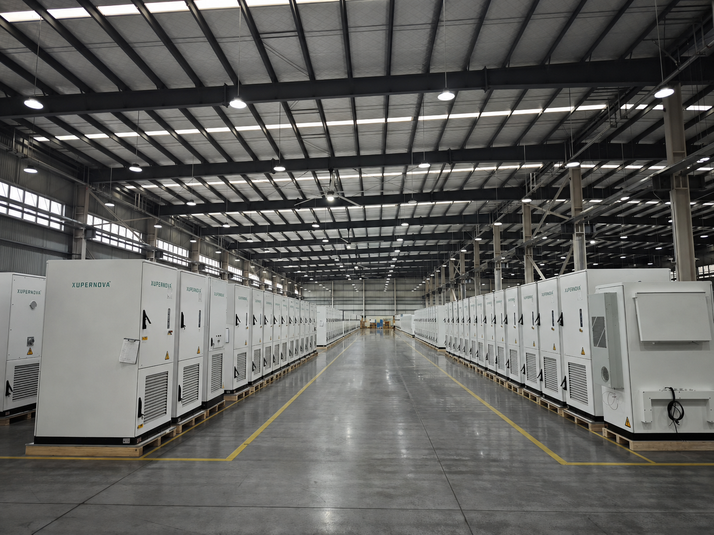
Xupernova manufacturing base, where 100% FAT with electrical safety, functional and aging tests is performed, with third-party inspection available on request.
To review the full configuration range before finalising a specification, download the Xupernova energy storage product catalog, or visit Xupernova New Energy Technology Co., Ltd. for technical documentation and project-specific compliance evidence.
Have Questions or Need More Details?
Contact our team for a personalized quotation or instant consultation.
Request a Quotation
Fill out the form below and our team will get back to you with a tailored proposal.
WhatsApp Direct Chat
Prefer to chat in real-time? Message us on WhatsApp for instant assistance & quick answers.
- Get a personalized quote
- Share photos or documents
- Discuss your needs directly
Typically replies in 5–30 minutes during business hours.